Suzuki 90-200HP outboard motors Service Manual, Page 4Get this manual
SERVICE MANUAL valves are properly synchronized as described in SPEED CONTROL LINKAGE sectionWith throttle in the fully closed position, clearance (C-FigSZIS-12) between boss (4) and control lever (3) should be less than 1.0 nlIn (0.0:,9 in, but lever (3) should not be touching boss (4)Loosen nuts jam nuts (N) and vary length of rod (2) to adjustGEAR COUNTER COILUnplug connectors leading from gear counter coil (8-FigSZIS-15)Connect tester between the orangegreen and the black!green wire eonneetorsResistance should be 160-230 ohmsAir gap between counter coil and the flywheel ring gear teeth should be 0.5 mm (0.020 inLoosen counter coil mounting screws and slide coils as necessary to adjust
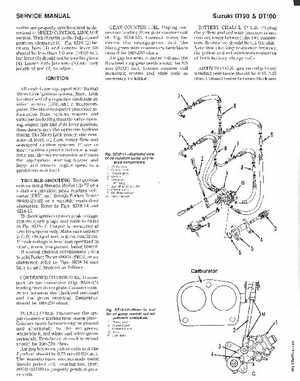
Suzuki OT90OT100
BATTERY CHARGE COILSUnplug the yellow and red wire connectors and connect tester between the two connectorsResistance should be 0.4-0.6 ohmNote that checking resistance between the yellow and red wires tests resistance of both battery charge coilsIGNITION COILSIgnition coil primary winding resistance should be 0.15-0.25 ohmConnect tester between black and