Suzuki 8-25HP outboard motors Service Manual, Page 20Get this manual
Suzuki DT20DT25 (Prior To 1983) whiteblack wire connector at coil and remove high tension wires from spark plugsAttach tester positive lead to black wire and negative lead to whiteblack wirePrimary coil resistance reading should be within the limits of 0.28-0.38 ohmsAttach tester lead to each high tension wireSecondary coil resistance reading should be within the limits of 2975-4025 ohmsTo check condition of CD module, use tester or ohmmeter in conjunction with test chart shown in FigSZ8-10Renew CD module if required
OUTBOARD MOTOR
COOLING SYSTEM
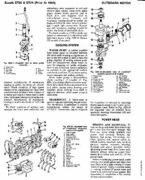
WATER PUMPA rubber impeller type water pump is mounted between the drive shaft housing and gearcaseA key in the drive shaft is used to turn the pump impellerIf cooling system problems are encountered, check water intake for plugging or partial stoppage, then if not corrected, remove gearcase as outlined in the appropriate section and check condition of the water pump, water passages and sealing surfacesWhen water pump is disassembled, check condition of impeller (7FigSZ8-11) and plate (8) for excessive wearTurn drive shaft clockwise (viewed from top) while placing pump housing over impellerAvoid turning drive shaft in opposite direction when water pump is assembledTHERMOSTATA thermostat is used to regulate operating temperatureThe thermostat is calibrated to control temperature within the range of 61-64CThermostat can be removed