1996-2005 Suzuki DF40, DF50 Four Stroke Outboard Service Manual, Page 90Get this manual
3-35 ENGINE CONTROL SYSTEM
INSPECTION FOR RESISTANCE
09930-99320Digital tester Tester range(Resistance)
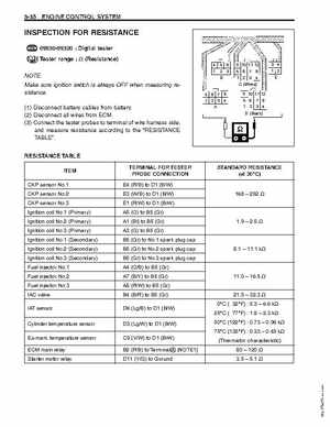
4 56 23 10 11 12 5678 1234 (White) 5678 1234 10 11 12 5678 1234 (Black) 34 12 E
NOTE: Make sure ignition switch is always OFF when measuring resistance(1) Disconnect battery cables from battery(2) Disconnect all wires from ECM(3) Connect the tester probes to terminal of wire harness side, and measure resistance according to the "RESISTANCE TABLE"RESISTANCE TABLE
ITEM CKP sensor No.1 CKP sensor No.2 CKP sensor No.3 Ignition coil No.1 (Primary) Ignition coil No.2 (Primary) Ignition coil No.3 (Primary) Ignition coil No.1 (Secondary) Ignition coil No.2 (Secondary) Ignition coil No.3 (Secondary) Fuel injector No.1 Fuel injector No.2 Fuel injector No.3 IAC valve IAT sensor Cylinder temperature sensor Ex-manitemperature sensor ECM main relay Starter motor relay TERMINAL FOR TESTER PROBE CONNECTION E4 (RB) to D1 (BW) E3 (WB) to D1 (BW) E1 (RW) to D1 (BW) A5 (O) to B5 (Gr) A1 (Bl) to B5 (Gr) A3 (G) to B5 (Gr) B5 (Gr) to No.1 spark plug cap B5 (Gr) to No.2 spark plug cap B5 (Gr) to No.3 spark plug cap A4 (OB) to B5 (Gr) A7 (BY) to B5 (Gr) A8 (RW) to B5 (Gr) B4 (BR) to B5 (Gr) D6 (LgB) to D1 (BW) D3 (LgW) to D1 (BW) C9 (VW) to D1 (BW) B2 (PB) to TerminalA [NOTE1] D11 (YG) to Ground