Mercury Optimax Models 135, 150, Direct Fuel Injection., Page 138Get this manual
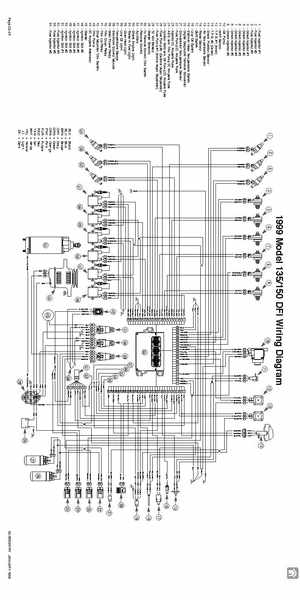
1999 Model 135150 DFI Wiring Diagram 1 6
1 10 11 12 13 14 15 16 17 18 19 20 21 22 23 24 25 26 27 28 29 30 31 32 33 34 35 36 37 38 39 40 41 42 43 44 45 46 47 48 49 50 51 52 53 54
BA PNKORG PNKBRN BRNPNK ORGPNK PNKRED REDPNK BA WHTBRN BRNWHT WHTORG ORGWHT WHTRED REDWHT BA BA BA BA BA WHTYEL YELWHT BA WHTDK.BLU DK.BLUWHT BA WHTPPL PPLWHT BLK PNKDK.BLU DK.BLUPNK GRNORG BLK REDYEL GRNBRN REDYEL GRNRED BLK REDYEL PNKPPL PPLPNK PNKYEL YELPNK REDYEL BLK BA BA BA ABC ABC ABC
Fuel Injector #1 Fuel Injector #2 Fuel Injector #3 Direct Injector #1 Direct Injector #2 Direct Injector #3 Direct Injector #4 Direct Injector #5 Direct Injector #6 Oil Pump MAP Sensor T.P.S#1 (Inner) T.P.S#2 (Outer) Crank Position Sensor Air Temperature Sensor Water Sensor Shift Switch Low-Oil Switch Cylinder Head Temperature Switch Digital Diagnostic Terminal Connector Compressor Temperature Sensor Fuel Pump 20 Ampere Fuse Injector 20 Ampere Fuse ACCand Trim Pump 20 Ampere Fuse Ignition Coils and Oil Pump 20 Ampere Fuse Fuel Pump #2 (Outside Vapor Separator) Fuel Pump #1 (Inside Vapor Separator) 12 Volt Battery Starter Solenoid To Remote Control Trim Switch Remote Control Auxiliary Check Engine Light Water In Fuel Light Over-Heat Light Low Oil Light Temperature Gauge Electronic Control Module Main Power Relay Trim Down Relay Trim Up Relay Cowl Mounted Trim Switch Trim Pump 60 Ampere Alternator Starter Ignition Coil #6 Ignition Coil #5 Ignition Coil #4 Ignition Coil #3 Ignition Coil #2 Ignition Coil #1 Fuel Injector #4 Fuel Injector #5 Fuel Injector #6