Mercury Optimax Models 135, 150, Direct Fuel Injection., Page 55Get this manual
IGNITION
ELECTRICAL
Section 2A Ignition
Table of Contents
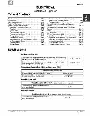
Specifications Special Tools Electrical Components Theory of Operation Ignition Component Description Electronic Control Module (ECM) Flywheel Ignition Coils Crank Position Sensor Throttle Position Sensor (TPS) Charging System Alternator Temperature Sensor Manifold Absolute Pressure (MAP) Sensor Air Temperature Sensor Direct Injectors Fuel Injectors 2A-1 2A-2 2A-4 2A-6 2A-6 2A-6 2A-7 2A-7 2A-7 2A-7 2A-7 2A-8 2A-9 2A-9 2A-9 2A-9 Disconnecting Harness Connectors from Ignition Coils andor Injectors 2A-9 Troubleshooting 2A-9 Troubleshooting Without Digital Diagnostic Terminal 2A-10 Troubleshooting With the Digital Diagnostic Terminal 2A-11 Notes 2A-12 DDT Functions 2A-13 DFI Troubleshooting Guide 2A-15 Ignition Components Removal and Installation 2A-18 Flywheel Cover Removal and Installation 2A-18 Electronic Control Module (ECM) 2A-19 Ignition Module (Coil) 2A-20 Crank Position Sensor 2A-21 Throttle Position Sensors (TPS) 2A-21