Mercury 35/40HP 2 Cylinder Outboards Service Manual PN 90-42794--1, Page 297Get this manual
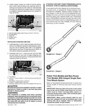
4Install rubber bumper on inside of locking sleeve, then install locking sleeve over steering cable attaching nut and secure with cotter pinSpread ends of cotter pin8e sure to install cotter pin so that it is located in between attaching nut and grease fitting, as shown STEERING LINK ARMPOWER TRIM MODELS WITH INTEGRAL TRIM CYLINDERS (3 RAM SYSTEM) new steering link arm (Design 2) for starboard steering cable entry, is available for models between SIN 8110789 thru 8239241 Replace original straight link arm (Design 1) with the new curved steering link arm (Design 2) on any unit that is serviced Reuse existing attaching parts (nuts, washers, bolts, etcOutboards above SIN 8239241 will have the new link arm in the steering attaching kit which is in the shipping carton new steering link arm PIN 17432A6, for port steering cable entry, is also available
Steering Cable Attaching Nut [Torque to 35 lb ft(47 Nm)] Locking Sleeve Cotter Pin Grease Fitting Cable End
INSTALLING STEERING LINK ROD 1Lubricate hole in end of steering cable with Quicksilver 2- 4-C Marine Lubricant and assemble steering link rod to steering cable with flat washers and locknut, as shownTorque locknut to 120 lbin (13.2 Nm) maximum and back off 14 turn 2Lubricate ball joint in steering link rod with 30W oil and install to rear hole in engine steering arm with pivot bolts and locknutTorque pivot bolt, then locknut to 20 lbft(27 Nm)Straight ArmDesign 1