Mercury 35/40HP 2 Cylinder Outboards Service Manual PN 90-42794--1, Page 20Get this manual
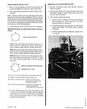
IGNITION (KEY) SWITCH TEST 1Refer to wiring diagram at end of this section for correct identification of ignition switch terminals2Disconnect battery leads from battery before making testsNOTE: Ignition switch can be checked without disassembling remote control assemblyRefer to wiring diagramsat end of this section and connect VOA meter to terminals (in remote control wiring harness connector) which are connected to terminals of key switch that are called out in the following tests3Set VOA meter on Rx1 scale for the following testsIMPORTANT: Make sure that battery leads are disconnected MERCURY (TILT) STOP SWITCH TEST 1Remove mounting screw that secures mercury switch to engine2Connect Ohmmeter (Rx1 scale) between black lead and either orange or blackyellow lead or terminal stud on mercury switch3Test mercury switch as follows: aPosition mercury switch as it would be installed when engine is in "down" position The meter should indicate no continuitybTilt mercury switch up, as shown, and tap end of switch with fingerThe meter should indicate continuitycIf these readings are not obtained, replace mercury switch