Mercury 35/40HP 2 Cylinder Outboards Service Manual PN 90-42794--1, Page 18Get this manual
Ignition System Descri ption
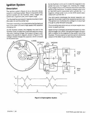
The ignition system (Figure A) is an alternator driven capacitor discharge systemMajor components of the ignition system are the flywheel, stator, trigger coil, switch box, ignition coils, and spark plugsThe flywheel has permanent magnets mounted in both the outer rim and the center hubThe stator assembly is mounted below the flywheel and has low speed (LS) and high speed (HS) capacitor charging coilAs the flywheel rotates, the magnets mounted in the flywheel outer rim pass the LS and HS capacitor charging coils, creating voltageCoil output voltage is indicated in the waveform diagram, shown in Figure AThe voltage created charges the capacitor, which is located in the switch boxFLYWHEEL STOP SWITCH
As the flywheel continues to rotate the magnets in the center hub pass the trigger coil, creating AC voltageThe voltage turns on one of the two electronic switches (SCR) in the switchboxA positive voltage pulse turns on the SCR switch associated with cylinder No.1; negative voltage pulse turns on the SCR switch associated with cylinder NO2The SCR switch discharges the stored capacitor voltage into the primary side of the respective ignition coilThe ignition coil multiplies this voltage to value high enough to jump the spark plug gapThe preceding sequence occurs once per engine revolution for each cylinderSpark timing is changed (advancedretarded) by rotating the trigger coil, which changes the trigger coil position in relation to the magnets in the center hub of the flywheelThe stop switch (or ignition switch) shorts the output of the stator to ground to stop the engine