1997+ Mercury 35/40HP 2 Cylinder Outboards Service Manual PN 90-826148R2, Page 129Get this manual
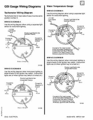
QSI Gauge Wiring Diagrams Tachometer Wiring Diagram
Tachometer dial on back side of case must be set to position number 4WIRING DIAGRAM Use this wiring diagram when using separate light switch for instrument lighting+12 Volt Light Switch Wire
Water Temperature Gauge
WIRING DIAGRAM Use this wiring diagram when using separate light switch for instrument lighting+12 Volt Light Switch Wire Position Light Bulb to the Switched Position
Position Light Bulb to the Switched Position onnect to egative () Ground
C onnect to12 Volt
C onnect to egative () Ground
C onnect to12 Volt
C onnect to Tan Le ad Located at the Tachometer eceptacle on ommander Side Mount emote ontrol or Tan Le ad oming From Accessory IgnitionC hoke Assembly
WIRING DIAGRAM Use this wiring diagram when instrument lighting is wired directly to the ignition key switch(Instrument lights are on when ignition key is turned on