1997+ Mercury 35/40HP 2 Cylinder Outboards Service Manual PN 90-826148R2, Page 65Get this manual
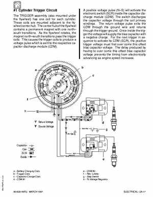
#1 Cylinder Trigger Circuit The TRIGGER assembly (also mounted under the flywheel) has one coil for each cylinderThese coils are mounted adjacent to the flywheel center hubThe center hub of the flywheel contains permanent magnet with one north south transitionsAs the flywheel rotates, the magnet northsouth transitions pass the trigger coilsThis causes the trigger coils to produce voltage pulse which is sent to the respective capacitor discharge module (CDM)
A positive voltage pulse (NS) will activate the electronic switch (SCR) inside the capacitor discharge module (CDM)The switch discharges the capacitor voltage through the coil primary windingsThe return voltage pulse exits the CDM through the ground wire and returns through the trigger groundOnce inside the trigger the voltage will supply the bias capacitor with negative chargeFor the next trigger in sequence to activate its CDM (SCR), the positive trigger voltage must first over come this offset bias capacitor voltageThe delay produced by having to over come this offset bias capacitor voltage prevents the timing from electronically advancing as engine speed increasesb