1984-1986 Mercury Force 9.9 and 15HP Outboards Service Manual, Page 65Get this manual
2Install impeller (rotate Impeller counterclockwise) Into pump bodyGroove for drive pi shou ld be open when viewed from bonom Figure 7 GEAR TRAIN
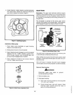
DescriptionThe gear train redirects vertical engine rotation to the propeller which is on horizontal plane when the engine is running Propeller rotation (forward or reverse) is controlled by the shifting mechan is of the gear train The driveshaft is splined to the pinion gear wh ich meshes with forward and reverse gearThe propeller shaft engages the gears by means olthe shift clutch
REAR GEAR
Figure 7, Initalllng Impeller, InltallatlonWater pump: 1Place water pump backplate on gear housing Make sure all holes line up 2Slide pump drive pin in hole driveshaftFigure 9, Operating of Gear Trai n3Apply liberal amount of grease to end of drives haft (S pecial Tool NoT 2961) Carefully guide shaft th rough impeller and driveshaft seal until pump drive pin engages slot in impeller4Apply sealant to threads of cap screws (Special Tool NoT 8983) Secure pumpThe shift clutch moves back and forth by following the clutch shift cam on the end of the shift rod When shifted Into neutralthe shift clutch centers itself between forward and reverse gear and does not contact either one With shill lever in reversethe shift clutch engages reverse gear and turns the propeller counterclockwise FORWARD