2008 Evinrude E-TEC 55MFE Technical Manual, Page 112Get this manual
ELECTRICAL AND IGNITION SENSOR TESTS
SENSOR TESTS
All sensor circuits are dependent on wiring and connections, EMM supplied current (5 V), and sensor resistanceThe supplied current flows through the wiring circuit and sensor before returning to the EMM
(1.85 mm)The acceptable clearance is 0.036 to 0.110 in(1 to 2.8 mm)
IMPORTANT: Use Evinrude Diagnostics software to monitor sensor circuit voltages or values
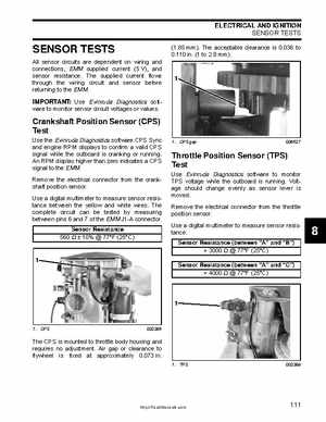
Crankshaft Position Sensor (CPS) Test
Use the Evinrude Diagnostics software CPS Sync and engine RPM displays to confirm valid CPS signal while the outboard is cranking or runningAn RPM display higher than zero indicates CPS signal to the EMMRemove the electrical connector from the crankshaft position sensorUse digital multimeter to measure sensor resistance between the yellow and white wiresThe complete circuit can be tested by measuring between pins and of the EMM J1-A connectorSensor Resistance 560 10 77F (25C)