2008 Evinrude E-TEC 55MFE Technical Manual, Page 111Get this manual
ELECTRICAL AND IGNITION GROUND CIRCUITS
GROUND CIRCUITS
All ground circuits are essential to reliable outboard performanceMake sure all ground connections are clean and tightRefer to wiring diagrams for specific wiring details
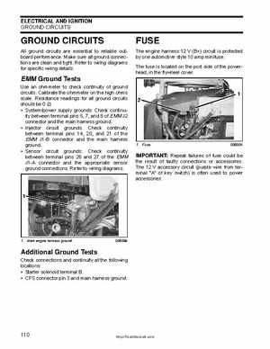
The engine harness 12 (B+) circuit is protected by one automotive style 10 amp minifuseThe fuse is located on the port side of the powerhead, in the flywheel cover
EMM Ground Tests
Use an ohmmeter to check continuity of ground circuitsCalibrate the ohmmeter on the high ohms scaleResistance readings for all ground circuits should be Systempower supply grounds: Check continuity between terminal pins 5, 7, and of EMM J2 connector and the main harness ground Injector circuit grounds: Check continuity between terminal pins 14, 20, and 21 of the EMM J1-B connector and the main harness ground Sensor circuit grounds: Check continuity between terminal pins 26 and 27 of the EMM J1-A connector and the appropriate sensor ground connectionsRefer to wiring diagrams