2007 Evinrude E-Tec 75, 90 HP outboards Service Manual, Page 127Get this manual
ELECTRICAL AND IGNITION IGNITION SYSTEM TESTS
IGNITION SYSTEM TESTS
Sensor Resistance Tests
All sensor circuits are dependent on wiring and connections, EMM supplied current (5 V), and sensor resistanceThe supplied current flows through the wiring circuit and sensor before returning to the appropriate circuit in the EMM
Throttle Position Sensor (TPS) Test
Disconnect the battery cables at the batteryRemove the electrical connector from the TPSUse an ohmmeter to measure sensor resistance
IMPORTANT: DO NOT lubricate TPS to throttle
shaft surfaceSTEP Connect red meter lead to terminal "A" and black meter lead to terminal "B Sensor Resistance (between "A" and "B")3000 77F (25C) Sensor Resistance (between "A" and "C")4000 77F (25C)
IMPORTANT: Use the Evinrude Diagnostics
Software program to monitor sensor circuit voltages or values
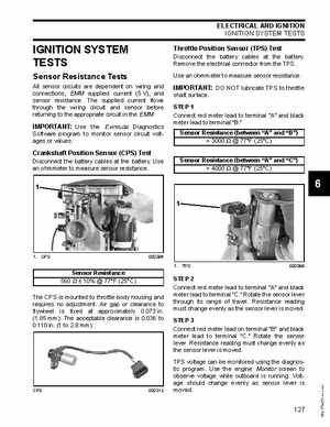
Crankshaft Position Sensor (CPS) Test
Disconnect the battery cables at the batteryUse an ohmmeter to measure sensor resistance