2007 Evinrude E-Tec 75, 90 HP outboards Service Manual, Page 104Get this manual
SYSTEM ANALYSIS ELECTRICAL CONNECTIONS
ELECTRICAL CONNECTIONS
Inspect wiring and electrical connectionsDisassemble and clean all corroded connectionsReplace damaged wiring, connectors, or terminalsRepair any shorted electrical circuitsRefer to wiring diagrams and reference charts to identify specific wiring details
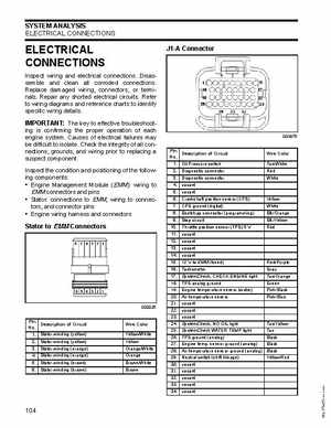
J1-A Connector
IMPORTANT: The key to effective troubleshooting is confirming the proper operation of each engine systemCauses of electrical failures may be difficult to isolateCheck the integrity of all connections, grounds, and wiring prior to replacing suspect componentInspect the condition and positioning of the following components: Engine Management Module (EMM): wiring to EMM connectors and pins Stator: connections to EMM, wiring to connectors, and connector pins Engine wiring harness and connectors
Stator to EMM Connectors
Pin No12345678910111213141516171819202122232425262728293031323334
Description of Circuit Oil Pressure switch Diagnostic connector Diagnostic connector vacant vacant Crankshaft position sensor (CPS) CPS ground (digital) Bootstrap connector (programming) Stop circuit Throttle position sensor (TPS) vacant vacant vacant vacant 12 to EMM (fused) Tachometer SystemCheck, CHECK ENGINE light TPS analog ground Engine temperature sensor (water) Air temperature sensor vacant vacant vacant SystemCheck, NO OIL light SystemCheck WATER TEMP light TPS ground (analog) Engine tempsensor ground (analog) Air temperature sensor ground (analog) Neutral switch (shift linkage) vacant vacant vacant vacant vacant