2004 SR Johnson 2-stroke 40, 50HP Service Manual, Page 132Get this manual
IGNITION TIMER BASE
Installation
Remove any varnish around retaining screw holes on both sides of statorThe stator must have metal to metal contact with the crankcase head and its retaining screws
TIMER BASE
40150 PL MODELS12 AMP
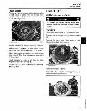
Removal
WARNING
To prevent accidental starting while servicing, twist and remove all spark plug leads
Remove the statorRefer to STATOR on p130Separate the timer base 3-pin Amphenol connectorRemove the three timer base retaining clipsRemove timer base from adapterScrew holes
Position the stator on adapter and route the leadsApply Nut Lock to mounting screwsInstall screws and torque them 120 to 144 in.lbs(14 to 16 Nm)Attach stator yellow and yellowgray leads to terminal boardCoat final connection with Black Neoprene DipInstall blackyellow stop circuit lead in 5-pin Amphenol connector, terminal E1