2004 SR Johnson 2-stroke 40, 50HP Service Manual, Page 86Get this manual
ELECTRICAL CHARGING SYSTEM TESTS Variable Load High Rate Discharge Test STEP Disconnect battery cables at the batteryConnect to 40 ammeter in series between the rectifierregulator red lead and the battery side of the starter solenoidConnect the outboard's battery cables Following the manufacturer's directions, connect the variable load tester (carbon pile) across the battery terminalsStevens Model NoLB-85 and Snap-on Model NoMT540D are examples of testers available WARNING
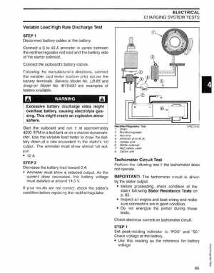
RectifierRegulator Test 1Stator 2Rectifierregulator 3Red wire 4Ammeter (0 to 40 A) 5Jumper wire 6Starter solenoid 7Red battery cable 8Carbon pile DRC7343
Excessive battery discharge rates might overheat battery, causing electrolyte gassingThis might create an explosive atmosphereStart the outboard and run it at approximately 4500 RPM in test tank or on marine dynamometerUse the variable load tester to draw the battery down at rate equivalent to the stator's full outputThe ammeter must show almost full output: 12 STEP Decrease the battery load toward Ammeter must show reduced outputAs the current draw decreases, the battery voltage must stabilize at around 14.5 VIf your results are not correct, check the stator's condition before replacing the rectifierregulator