2004 SR Johnson 2-stroke 40, 50HP Service Manual, Page 12Get this manual
INTRODUCTION TYPICAL PAGED
TYPICAL PAGED
OILING SYSTEM COMPONENTS
Two pulse hoses connect the pump to pulse fittings on the front of the cylindercrankcase V4 Modelscylinders and V6 Modelscylinders and 4
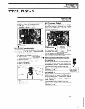
Oil Pressure Switch
The oil pressure switch is located in the oil injector-manifold and reacts to changes in oil manifold pressureThe EMM supplies and monitors electrical current to the switch
anifold distributes the oil suplift pumpA pressure-sensing monitors oil injection pressure
The switch opens or oil manifold pressures:
components numbered to correspond to image
Oil Injector-Manifold
Oil pressure switch Pressure regulator (oil return hose) Oil distribution hoses Oil to fuel check valve
C:POlDClDalDt5=_ 40 oil injector Cross references Oil distribution manifold direct readers to rel ated topics
53 psi (365 kPa) (nominal) to close 43 psi (296 kPa) (nominal) to reopen