2000 Johnson/Evinrude SS 25, 35 3-Cylinder outboards Service Manual, Page 99Get this manual

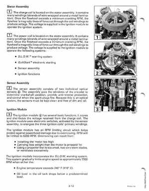
Stator Assembly The charge coil is located on the stator assemblyIt contains many windings (strands of wire wrapped around metal lamination)Once the flywheel exceeds minimum cranking RPM, the flywheel's magnetic lines of force cut through the coil windings to produce voltageThe voltage is supplied to the ignition module to operate the ignition system
The power coil is located on the stator assemblyIt contains many windings (strands of wire wrapped around metal lamination)Once the flywheel exceeds minimum cranking RPM, the flywheel's magnetic lines offorce cut through the coil windings to produce voltageThe voltage is supplied to the ignition module to operate the following systems: S.L.oWTof
warning system
QuikStartTof electronic starting
Sensor assembly Ignition functions Sensor Assembly
m The.sensor assembly uses the windows of the encoder to assembly consists of two individual optical The sensors