1999 Evinrude "EE" Electric Outboards Service Manual, P/N 787021, Page 45Get this manual
Resistor AssemblyHBF2 Models Only perform this check after completing Motor Tube Wiring ResistorHBF2 Models checks [I]
1Remove two thru-bolts and remove motor drive-end head, motor field, and motor armatureDo not lose armature brush springs
2Use an ohmmeter calibrated on high ohms scale or continuity light to test continuity
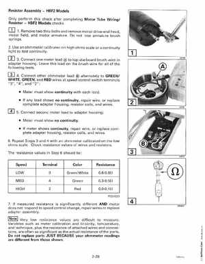
3Connect one meter lead to top starboard brush wire in adapter housingLeave this lead on the brush wire for all of the following tests
4Connect other ohmmeter lead alternately to GREEN WHITE, GREEN, and RED wires at speed control switch terminals "3", "4", and "2": Meter must show continuity with each lead If any lead shows no continuity, repair wireor replace complete adapter housing, resistor coils, and wires 5Connect second meter lead to adapter housingMeter must show no continuity If meter shows continuity, repair wire, or replace complete adapter housing, resistor coils, and wires