1999 "EE" Evinrude 5 thru 15 4-Stroke Service Manual, P/N 787022, Page 89Get this manual
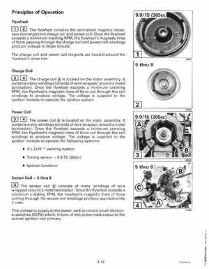
Principles of Operation Flywheel
The flywheel contains the permanent magnets necessary to energize the charge coil and power coilOnce the flywheel exceeds minimum cranking RPM, the flywheel's magnetic lines of force passing through the charge coil and power coil windings produce voltage in those circuits
The charge coil and power coil magnets are located around the flywheel's inner rim
Charge Coil
The charge coil is located on the stator assemblyIt contains many windings (strands of wire wrapped around metal lamination)Once the flywheel exceeds minimum cranking RPM, the flywheel's magnetic lines of force cut through the coil windings to produce voltageThe voltage is supplied to the ignition module to operate the ignition system
Power Coil
The power coil is located on the stator assemblyIt contains many windings (strands of wire wrapped around metal lamination)Once the flywheel exceeds minimum cranking RPM, the flywheel's magnetic lines of force cut through the coil windings to produce voltageThe voltage is supplied to the ignition module to operate the following systems: