1999 "EE" 90, 115 FFI, 150, 175 V4, V6 FFI Outboards Service Manual, P/N 787024, Page 85Get this manual

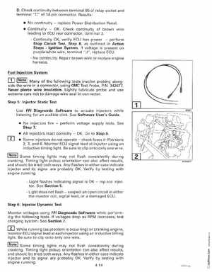
DCheck continuity between terminal 85 of relay socket and terminal "C" of 14-pin connectorResults: No continuityreplace Power Distribution Panel ContinuityOKCheck continuity of brown wire leading to ECU rear connector, terminal 3- Continuity OK, verify ECU has powerperform Stop Circuit Test, Step 8, as outlined in Action StepsIgnition SystemIf voltage is present on purplewhite wire, terminal "J", replace ECU- No continuityRepair brown wire or replace engine harnessFuel Injection System]Notel Many of the following tests involve probing alongside the wire in connector, using O'VIC Test Probe, PIN 342677Never pierce wire insulationLightly lubricate probe and use extreme care not to damage wire seal in connectorStep 5: Injector Static Test Use FFI Diagnostic Software to actuate injectors while listening for an audible clickSee Software User's Guide No injectors fireperform voltage supply testsSee Step All injectors react correctlyOKGo to Step 6 I]]