1998 Johnson Evinrude "EC" 125C, 130, 200, 225, 250 90 deg LV Service Manual, P/N 520212, Page 170Get this manual
Sensor Coil Ohmmeter Test
All ohmmeter tests must be performed with engine NOT running
1Before proceeding, you must verify that the ohmmeter red lead is the "+" leadCalibrate meter on appropriate scaleAttach to known good diode as shown Meter must show low reading When meter leads are reversed, meter must show high reading2If your test results are opposite, reverse internal meter lead connections so the red lead represents "+"
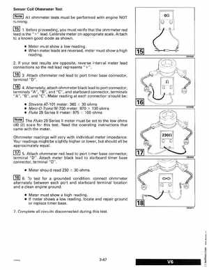
3Attach ohmmeter red lead to port timer base connector, terminal "0"
4Alternately, attach ohmmeter black lead to port connector, terminals "A", "B", and "C", and starboard connector, terminals "A""B", and "C"Meter reading at each connection should be:
Stevens AT-101 meter: 360 30 ohms Merc-O- Tronic M-700 meter: 970 100 ohms Fluke 29 Series II meter975 100 ohms
The Fluke 29 Series II meter must be set to the low ohms (40 0) scale for this testRead the operating instructions that came with the meter