1997 Johnson Evinrude "EU" Electric Outboards Service Manual, P/N 507260, Page 34Get this manual

P.W.MController and Motor Test
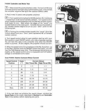
1Disconnect the positive battery cableConnect 0-50 amp ammeter positive lead to the positive battery post, and connect the ammeter negative lead to the positive battery cable2Place motor in water with propeller attached
rn 3Turn speed controlofwheel to SLOW position (full clockwiseviewed from shaft end variable resistor)Turn speed control
wheel slightly counterclockwise until you feel the variable resistor shaft begin to turn Note where the edges of the "panel" are located relative to the index pointConsider this point just before the variable resistor begins to turn as your "Zero" point for the following test
rn 4Turningfromvariable resistor exactly one "panel" on the the control wheel your "Zero" point represents 45 of variable
resistor rotation5Turn speed control wheel to each position starting with your Zero position, push ONOFF switch, and note amperage reading You will hear the relay in the controller click when the ONOFF switch is pushedAt zero degree, the propeller should not turn6When the speed control is turned beyond the No6 position, up to the Maxposition with the ONOFF switch held down, you will hear the high-bypass relay clickThe amperage should jump up slightly as the speed control circuit is bypassed and full battery voltage is connected to the motorTotal P.W.MElectric Outboard Motor Current Speed Control Position MaxAngle