1997 Johnson Evinrude "EU" Accessories Service Manual, P/N 507270, Page 197Get this manual
NO OIL Circuit 1Separate the VRO pump 4-pin Amphenol connector[] 2Using jumper wire, connect the engine harness tan yellow wire, terminal "A", and black wire, terminal "B", together3Turn the key switch to ON positionAfter the normal self-test sequence, the gauge NO OIL light should stay on If the NO OIL light is not on, troubleshoot the tanyellow and black circuits for an open in the engine harness or the instrument harness4Turn the key switch OFF and reconnect all circuits disconnected during these tests5To verify the VRO pump warning circuit, refer to VRol Warning Signals, Section 2, NO OIL signal test in your engine OMC Service ManualCHECK ENGINE Circuit
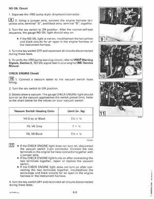
1Connect vacuum tester to the vacuum switch hose fitting2Turn the key switch to ON position3Slowly draw vacuumThe gauge CHECK ENGINE light should turn on as the vacuum approaches the switch preset limitRefer to the chart below for the values on your vacuum switch