1997 Johnson Evinrude "EU" 40 thru 55 2-Cylinder Service Manual, P/N 507265, Page 318Get this manual
8Reinstall UP relayPush blades only halfway into UP (blue) end of bracket m 9Push UP trim button and check for voltage at
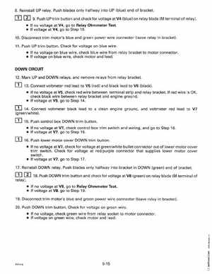
V4 (blue) on relay blade (M terminal of relay)
If no voltage at V4, go to Relay Ohmmeter Test If voltage at V4, go to Step 1010Disconnect trim motor's blue and green power wire connector (leave relay in bracket)11Push UP trim buttonCheck for voltage on blue wire If no voltage on blue wire, check blue wire from relay bracket to motor connector If voltage on blue wire, check motor and leadDOWN CIRCUIT
12Mark UP and DOWN relays, and remove relays from relay bracket13Connect voltmeter red lead to V5 (red) and black lead to V6 (black) If no voltage at V5, check red wire between terminal strip and relay bracketIf red wire is OK, check black wire between relay bracket and engine ground If voltage at V5, go to Step 14
14Connect voltmeter black lead to clean engine ground, and voltmeter red lead to V7 (greenwhite)15Push control box DOWN trim button If no voltage at V7, check control box trim switch and wiring, and go to Step 16 If voltage at V7, go to Step 1616Push lower motor cover DOWN trim button If no voltage at V7, check for voltage at greenwhite bullet connector out of lower motor cover trim switchCheck for voltage at redpurple connector that supplies lower motor cover switch If voltage at V7, go to Step 17