1997 Johnson Evinrude "EU" 125C, 130, 200, 225, 250 90 LV Service Manual, P/N 507269, Page 131Get this manual
Principles of Operation Flywheel
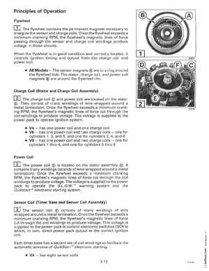
The flywheel contains the permanent magnets necessary to energize the sensor and charge coilsOnce the flywheel exceeds minimum cranking RPM, the flywheel's magnetic lines of force passing through the sensor and charge coil windings produce voltage in those circuitsWhen the flywheel is in good condition and correctly located, it controls ignition timing and output from the charge coil and power coil All ModelsThe sensor magnets are in ring around the flywheel hubThe stator, charge coil, and power coil magnets are around the flywheel rim
Charge Coil (Stator and Charge Coil Assembly)
rnThey charge coil many windingscoil are located on the stator The and power consist of of wire wrapped around a