1996 Johnson Evinrude "ED" Electric Outboards Service Manual, P/N 507119, Page 42Get this manual
Speed Control SwitchHand Control Models
INote To avoid damaging components or troubleshooting equipment, disconnect the battery cables before proceeding
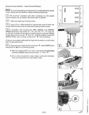
The terminal numbers and their locations on the speed control switch are as shown (terminal side of switch)1Remove steering housing coverB
2Use 1fa inAllen wrench to remove the control shaft set screwRemove the control shaft and forwardreverse lever
c:::::::::J c:::::::::JDR4798
3Unsolder and remove the RED, GREEN, and GREEN! WHITE wires from terminals "2", "3", and "4" ("1", "2" and "4" on 12-volt models) of the speed control switch (and two WHITE 16-Gawires on terminals "3" and "4", 12-Volt models)Leave the WHITE 12-Gawire in place on terminal "B" during testing4Use an ohmmeter calibrated on high ohms scale or continuity light to test continuity[] 5Connect one meter lead to terminal "B" (with WHITE wire attached) for all of the following tests With the switch OFF, the meter must show no continuity between WHITE lead and terminals "1" thru "4" At no time should the meter show continuity between any terminal and the metal switch case