1996 Johnson Evinrude "ED" 60 LV 90, 115, 150, 150C, 175 Service Manual, P/N 507127, Page 111Get this manual
Principles of Operation Flywheel
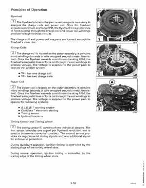
The flywheel contains the permanent magnets necessary to energize the charge coils and power coilOnce the flywheel exceeds minimum cranking RPM, the flywheel's magnetic lines of force passing through the charge coil and power coil windings produce voltage in those circuits
The charge coil and power coil magnets are located around the flywheel's inner rimCharge Coils]The charge coil is located on the stator assemblyIt contains many windings (strands of wire wrapped around metallamination) Once the flywheel exceeds minimum cranking RPM, the flywheel's magnetic lines offorce cut through the coil windings to produce voltageThe voltage is supplied to the power pack to operate the ignition system V4has one charge coil V6has two charge coils Power Coil]The power coil is located on the stator assemblyIt contains many windings (strands of wire wrapped around metallamination)Once the flywheel exceeds minimum cranking RPM, the flywheel's magnetic lines offorce cut through the coil windings to produce voltageThe voltage is supplied to the power pack to operate the following systems: