1995 Johnson/Evinrude Outboards 40 thru 55 2-Cylinder Service Manual, Page 113Get this manual
Principles of Operation Flywheel
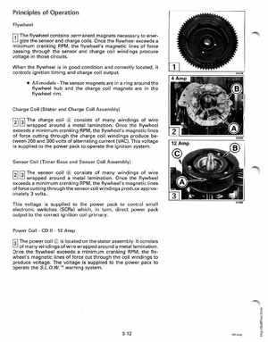
'11 The flywheel contains permanent magnets necessary to ener-
gize the sensor and charge coilsOnce the flywheel exceeds minimum cranking RPM, the flywheel's magnetic lines of force passing through the sensor and charge coil windings produce voltage in those circuitsWhen the flywheel is in good condition and correctly located, it controls ignition timing and charge coil output All modelsThe sensor magnets are in ring around the flywheel hub and the charge coil magnets are in the flywheel rimCharge Coil (Stator and Charge Coil Assembly)
121 fJl The
charge coil consists of many windings of wire wrapped around metal laminationOnce the flywheel exceeds minimum cranking RPM, the flywheel's magnetic lines of force cutting through the charge coil windings produce between 200 and 300 volts of alternating current (VAC)This voltage is supplied to the power pack to operate the ignition system