1995 Johnson Evinrude "EO" 90 CV 85 thru 115 Service Manual, P/N 503150, Page 101Get this manual
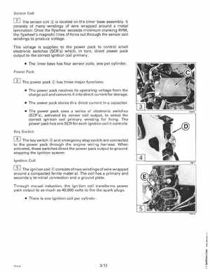
The sensor coil is located on the timer base assemblyIt consists of many windings of wire wrapped around metal laminationOnce the flywheel exceeds minimum cranking RPM, the flywheel's magnetic lines of force cut through the sensor coil windings to produce voltageThis voltage is supplied to the power pack to control small electronic switches (SCR's) which, in turn, direct power pack output to the correct ignition coil primary The timer base has four sensor coils; one per cylinderPower Pack
Sensor Coil
[]] The power pack
has three major functions:
The power pack receives its operating voltage from the charge coil and converts it into direct current for storage The power pack stores this direct current in capacitor The power pack uses series of electronic switches (SCR's), activated by sensor coil output, to select the correct ignition coil primary winding for firingThe power pack has one SCR for each ignition coil it controls