1994 Johnson/Evinrude Outboards 40 thru 55 Service Manual, Page 239Get this manual
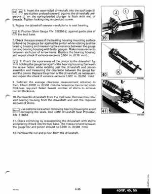
13811391 4Insert the assembled driveshaft into the tool base
and tighten preload screw CD against the driveshaft until groove Q) on the spring-loaded plunger is flush with end of threadsTighten locking ring on preload screw5Rotate the driveshaft several revolutions to seat bearing
1401 6Position Shim Gauge PIN 328366 against guide pins of
the tool base7Check the squareness ofthe bearing housing mounting surface by holding the gauge bar against the pinion while rotating just the bearing housing and measuring the clearance between the gauge bar and bearing housing with feeler gaugesMake measurements between each pair of screw holesReplace the bearing housing and repeat check if variance exceeds 0.004 in(0,10 mm)8Check the squareness of the pinion to the driveshaft by holding the gauge bar against the bearing housing (between the screw holes) while rotating just the driveshaft and pinion assembly and measuring the clearance between the gauge bar and the pinionReplace the pinion or the driveshaft, as necessary, and repeat the check if variance exceeds 0.002 in(0,050 mm)9Subtract the average clearance measurement obtained in Step from 0.020 in(0,508 mm) to determine the correct shim thickness requiredSelect fewest number of shims to achieve correct thickness10Remove the driveshaft from the tool baseRemove the collar and bearing housing from the driveshaft and add the required amount of shimsUse extreme care when removing bearing housing to avoid damaging the sealsUse OMC Driveshaft Seal Protector,