1994 Johnson/Evinrude Outboards 40 thru 55 Service Manual, Page 188Get this manual
26 Installation
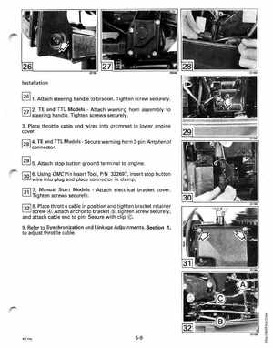
2 6 1Attach steering handle to bracketTighten screw securely27 2TE and TTL ModelsAttach warning horn assembly to steering handleTighten screws securely3Place throttle cable and wires into grommet in lower engine cover28 4TE and TTL ModelsSecure warning horn 3-pin Amphenol connector29 5Attach stop button ground terminal to engine30 6Using OMCPin Insert Tool, PIN 322697, insert stop button wire into plug and place connector in clampf31l 7Manual Start ModelsAttach electrical bracket coverTighten screws securely1321 SPlace throttle cable in position and tighten bracket retainer screw Attach anchor to brackettighten screw securely, and attach cable end to pinSecure with clip 9Refer to Synchronization and Linkage Adjustments, Section 1, to adjust throttle cable