1994 Johnson/Evinrude Outboards 40 thru 55 Service Manual, Page 120Get this manual
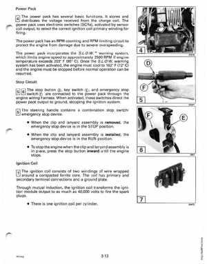
Power Pack
power pack has several basic functionsIt stores and distributes the voltage received from the charge coilThe power pack uses electronic switches (SeRs), activated by sensor coil output, to select the correct ignition coil primary winding for firing
The power pack has an RPM counting and RPM limiting circuit to protect the engine from damage due to severe overspeedingThe power pack incorporates the S.L.DWTM warning system, which limits engine speed to approximately 2500 RPM if engine temperature exceeds 203 (950 e)Once the S.L.OWwarning system has been activated, the engine must cool to 1620 (72 e) and the engine must be stopped before normal operation can be resumedStop Circuit
Isllsl The Isl The
stop buttonkey switchand emergency stop switch are connected to the power pack through the engine wiring harnessWhen activated, these switches direct the power pack output to ground, stopping the ignition system steering contains combination stop switch emergency stop device When the clip and lanyard assembly is removed, the emergency stop device is in the STOP position When the clip and lanyard assembly is installed, the emergency stop device is in the RUN position To stop the engine when the clip and lanyard assembly is in place, press the stop button inward until the engine stopsIgnition Coil