1994 Johnson/Evinrude "ER" 60 thru 70 outboards Service Manual, Page 131Get this manual
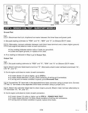
11 STEPSENSOR COIL TESTQUIKSTART MODELS
Ground Test
[!II 1Disconnect the 5-pin Amphenol connector between the timer base and power pack2Set peak-reading voltmeter to "POS" and "5", "SEN" and "5" on Stevens CO-77 meter1,1l3Alternately, connect voltmeter between each timer base terminal and clean engine groundCrank engine and observe meter at each connection Any reading indicates sensor coils or leads are grounded Locate and repair ground, or replace timer base4If no reading is indicated in Step 3, go to Output TestOutput Test 1Set peak-reading voltmeter to "POS" and "5", "SEN" and "5" on Stevens CO-77 meter
r:;:;l12 2Attach voltmeter black lead to terminal liE"Alternately attach meter red lead to terminals "A", "B", and "C"3Crank engine and observe meter at each connection If meter shows 1.5 volt or higher, go to STEP If meter shows less than 1.5 volt, check condition of wiring and connectors If wiring and connector condition is good, go to Ohmmeter Testf13l4Connect the "0" terminals in the separated timer base connector using jumper wireConnect the "E" terminals in the separated timer base connector using jumper wire