1994 Johnson Evinrude "ER" 60 LV 150, 150C, 175 Service Manual, P/N 500611, Page 278Get this manual
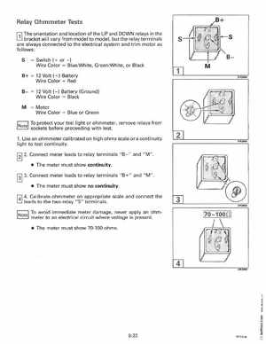
Relay Ohmmeter Tests r:;l The orientation and location ofthe UP and DOWN relays in the L!J bracket will vary from model to model, but the relay terminals are always connected to the electrical system and trim motor as follows:
= Switch (+ or -)
Wire ColorBluelWhite, GreenIWhite, or Black
12 Volt (+) Battery Wire ColorRed (-) Battery (Ground) Wire ColorBlack
Motor Wire ColorBlue or Green
To protect your test light or ohmmeter, remove relays from soc(.ets before proceeding with test1Use an ohmmeter calibrated on high ohms scale or continuity light to test continuity2Connect meter leads to relay terminals "B-" and "M" The meter must show continuityDR3950