1993 Johnson Evinrude "ET" Electric Outboards Service Manual, P/N 508280, Page 44Get this manual
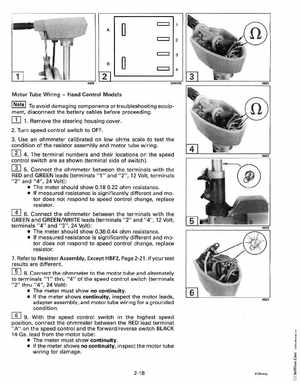
c::::J c::::J c::::JMotor Tube WiringHand Control Models
INote To avoid damaging components or troubleshooting equip-
ment, disconnect the battery cables before proceeding1Remove the steering housing cover
2Turn speed control switch to OFF3Use an ohmmeter calibrated on low ohms scale to test the condition of the resistor assembly and motor tube wiring
rn 4The terminal numbers and their locations on the speed control switch are as shown (terminal side of switch)rn andConnect the ohmmeter between the terminalsterminals 5with the RED GREEN leads (terminals "1" and "2",12 Volt, rn 6Connect the ohmmeter between the"2" and "4",12 Volt, terminals with the GREEN and GREENWHITE leads (terminals
"2" and "4", 24 Volt): The meter should show 0.18-0.22 ohm resistance If measured resistance is significantly different and motor does not respond to speed control change, replace resistor
terminals "4" and "3", 24 Volt): The meter should show 0.36-0.44 ohm resistance If measured resistance is significantly different and motor does not respond to speed control change, replace resistor7Refer to Resistor Assembly, Except HBF2, Page 2-21, if your test results are different