1993 Johnson Evinrude "ET" 90 degrees CV Service Manual, P/N 508285, Page 142Get this manual
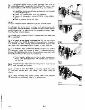
r:;l1115 modelsIf fi IIer blocks were removed, they must be LJ installed flush with the cylinder blockNew filler blocks must be machined flush with cylinder block after they are installed Install filler blocks using brass screws and coat threads with OMC Ultra Lock Center and lower screws must use lock tabs Tighten all screws to torque of 30-54 inIbs(3,4-6,1 Nm) Bend up outside tab of lock tabs I3J [!] 2Install the water deflectors in the cylinder block3Lubricate the center main bearings and split sleeves with Evinrude or Johnson Outboard Lubricant and install them in their original positionsThe split sleeve ring grooves must face away from flywheel when installedf414Place bearing retainer plateflat side down, on lower end of crankshaftf415To install new lower main bearing: Oil the end of the crankshaftUse OMC Crankshaft BearingSleeve Installer, PIN 338648, and place bearing onto crankshaft with lettered side facing the toolInstall bearing until it seats in the crankshaft1sl6To install new crankshaft sleeve: Oil the end of the crankshaftPlace the sleeve in OMC Crankshaft Bearingl Sleeve, PIN 338648, and drive the sleeve onto the crankshaft until the installer contacts the lower main bearing If the installer sticks on the sleeve after installation, thread OMC Slide Hammer, PIN 391008, into installer and pull offInspect sleeve surface after installingSleeve must not be used if surface is damaged1sl7Lubricate new driveshaft a-ring and lightly lubricate crankshaft splines with OMC Moly LubeInstall a-ring in sleevef.718Using retaining ring pliers, install lower main bearing retaining ring with sharp edge of ring facing out