1993 Johnson Evinrude "ET" 90 degrees CV Service Manual, P/N 508285, Page 97Get this manual
Principles of Operation Flywheel
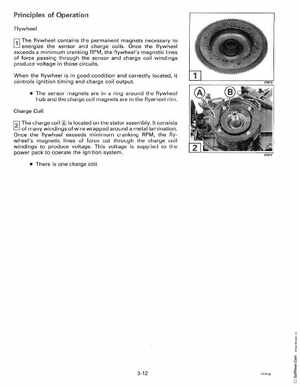
f1l The flywheel
contains the permanent magnets necessary to energize the sensor and charge coilsOnce the flywheel exceeds minimum cranking RPM, the flywheel's magnetic lines of force passing throwgh the sensor and charge coil windings produce voltage in those circuits
When the flywheel is in good condition and correctly located, it controls ignition timing and charge coil output The sensor magnets are in ring around the flywheel hub and the charge coil magnets are in the flywheel rimCharge Coil The charge coil is located on the stator assemblyIt consists of many windings of wire wrapped around metal laminationOnce the flywheel exceeds minimum cranking RPMthe flywheel's magnetic lines of force cut through the charge coil windings to produce voltageThis voltage is supplied to the power pack to operate the ignition system There is one charge coil