1993 Johnson Evinrude "ET" 60 thru 70 Service Manual, P/N 508284, Page 107Get this manual
Principles of Operation Flywheel
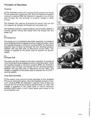
r;J The flywheel contains the magnets which energize the charge L!J coil, power coil, and sensor coilsOnce the flywheel exceeds minimum cranking RPM, the flywheel's magnetic lines of force pass through the coil windings to produce voltage in those circuits
The flywheel hub magnets energize the sensor coils and the rim magnets energize the charge coil and power coilThe flywheel must be in good condition and correctly locatedIt controls ignition timing and output from the charge coil and power coilCharge Coil The charge coil is located on the stator assemblyIt consists of many windings of wire wrapped around metal laminationOnce the flywheel exceeds minimum cranking RPM, the flywheel's magnetic lines of force cut through the coil windings produce between 200 and 300 volts of alternating current (VAC)The voltage is supplied to the power pack to operate the ignition system