1993 Johnson Evinrude "ET" 40 thru 55 Service Manual, P/N 508283, Page 298Get this manual
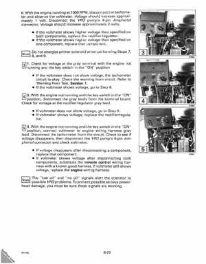
6With the engine running at 1000 RPM, disconnect the tachometer and observe the voltmeterVoltage should increase approximately voltDisconnect the VRO pump's 4-pin Amphenol connectorVoltage should increase approximately volts If the voltmeter shows higher voltage than specified on both components, replace the rectifierregulator If the voltmeter shows higher voltage than specified on one component, replace that component c=J Do not energize primer solenoid when performing Steps 7,
8, and 9Check for voltage at the gray terminal with the engine not running and the key switch in the "ON" position If the voltmeter does not show voltage, the tachometer circuit is okayCheck the warning horn circuitRefer to Warning Horn Test, Section If the voltmeter shows voltage, go to Step 88With the engine not running and the key switch in the "ON" position, disconnect the gray leads from the terminal board Check for voltage at the rectifierregulator gray lead If voltmeter does not show voltage, go to Step If voltmeter shows voltage, replace the rectifierregulatorf'5l 9With the engine not running and the key switch in the "ON" position, connect voltmeter to engine wiring harness gray leadDisconnect the tachometer from the circuitCheck to see if voltage disappears, then disconnect the VRO pump's 4-pin Amphenol connector and check voltmeter If voltage disappears after disconnecting component, replace that component If voltmeter shows voltage after disconnecting both components, substitute the remote control wiring harness with known good harnessIf voltmeter still shows voltage, replace the engine wiring harness