1993 Johnson Evinrude "ET" 40 thru 55 Service Manual, P/N 508283, Page 220Get this manual
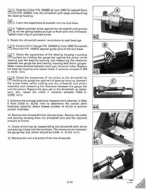
1421 2Slide the Collar PIN 334985 from OMC Driveshaft Shim Kit PIN 433032 onto the driveshaft with large end touching the bearing housing42 13Insert the assembled driveshaft into the tool base 1431 4Tighten preload screw against the driveshaft until groove on the spring-loaded plunger is flush with end of threadsTighten lock ring on preload screw5Rotate the driveshaft several revolutions to seat bearings1441 6Position Shim Gauge PIN 334984 from OMC Driveshaft Shim Kit PIN 433032 against guide pins of the tool base1451 7Check the squareness of the bearing housing mounting surface by holding the gauge bar against the pinion while rotating just the bearing housing and measuring the clearance between the gauge bar and bearing housing with feeler gaugesMake measurements between each pair of screw holesReplace the bearing housing and repeat check if variance exceeds 0.004 in(0,10 mm)1461 Check the squareness of the pinion to the driveshaft by holding the gauge bar against the bearing housing, between the screw holes, while rotating just the driveshaft and pinion assembly and measuring the clearance between the gauge bar and the pinionReplace the gear set or the driveshaft, as necessary, and repeat the check if variance exceeds 0.002 in(0,050 mm)9Subtract the average clearance measurement obtained in Step from 0.030 in(0,762 mm) to determine the correct shim thickness requiredSelect fewest number of shims to achieve correct thickness10Remove the driveshaft from the tool baseRemove the collar and bearing housing from the driveshaft and add the required amount of sh ims11Check shimm ing by reassembling the driveshaft with shims and placing it back into the tool baseThe measurement between the gauge bar and pinion should be 0.030 in(0,762 mm)12Remove the nut and pinion from the driveshaft