1992 Johnson Evinrude "EN" Electric Outboards Service Manual, P/N 508140, Page 37Get this manual
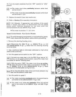
10Turn the switch clockwise from theOFF" position to "JOG" position The meter must show continuity between white lead and terminal The meter must show no continuity between white lead and terminals 1, 3, 411Replace the switch if your test results vary12Refer to Section for assembly information 12 ModelsIf appropriate, test condition of the speed resistor wire while it is disconnected from the speed control switch Calibrate ohmmeter on low ohms scale and connect between the two WHITE 16 ga oleads The meter must show 1.1 O.1 ohm Speed Control SwitchFoot Control Models INotel To avoid damaging components or troubleshooting equipment, disconnect the battery cables before proceeding1Remove the steering housing cover2Disconnect the RED 14 gaoGREEN 18 gao and GREENWHITE 18 gao leads from the steering housing terminal strips3Use continuity light or ohmmeter calibrated on high ohms scale to test continuity4Turn the speed control switch to the "OFF" position 5Connect one meter lead to the RED 16 gao lead at "A" terminal on the speed control switchLeave this meter lead connected for all the following tests 6With the switch "OFF," the meter must show no continuity when the second meter lead is connected to the RED 14 gaoGREEN 18 gao and GREENWHITE 18 gao leads coming from the foot pedal wiring harnessINotel At no time should the meter show continuity between any lead and the switch's metal case7Turn the switch to speed The meter must show continuity when the second lead is connected to the GREENWHITE 18 gao lead VI ID