1992 Johnson Evinrude "EN" 60 thru 70 Service Manual, P/N 508144, Page 327Get this manual
2 DR2065 DR2066
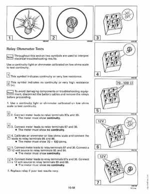
Relay Ohmmeter Tests
Throughout this section two symbols are used to interpret electrical troubleshooting resultsUse continuity light or ohmmeter calibrated on low ohms scale to test continuity] This symbol indicates continuity or very low resistanceThis symbol indicates no continuity or very high resistance
(00)DR2149
To avoid damaging components or troubleshooting equipo ment, disconnect the battery cables and remove the relays before proceeding1Use continuity light or ohmmeter calibrated on low ohms scale to test continuity
[!] 2Connect meter leads to relay terminals 87a and 30 The meter must show continuity0 3Connect meter leads to relay terminals 87 and 30 The meter must show no continuity4Calibrate an ohmmeter on low ohms scale and connect the leads to relay terminals 85 and 86 The meter must show 70100 ohms5Connect meter leads to relay terminals 87 and 30Connect 12 volt source to relay terminals 85 and 86 The meter must show continuity0 6Connect meter leads to relay terminals 87a and 30Connect 12 volt source to relay terminals 85 and 86 The meter must show no continuity7Replace relay if your test results varyDR2149