1992 Johnson Evinrude "EN" 40 thru 55 Service Manual, P/N 508143, Page 331Get this manual
B+ DR3944
DR3950a
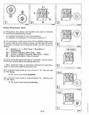
Relay Ohmmeter Tests
rv Throughout this section two symbols are used to interpret electrical troubleshooting results:
indicates continuity or very low resistanceindicates no continuity or very high resistance (00 )
f2l The orientation and location ofthe UP and DOWN relays in the
Switch (+ .or -), (Wire ColorBlueWhite or GreenIWhite)B+12 Volt (+) Battery, (Wire ColorRed)B-12 Volt (-) Battery (Ground), (Wire ColorBlack)MMotor, (Wire ColorBlue or Green)=
bracket will vary from motor to motor, but the relay terminals are always connected to the electrical system and trim motor as follows: S