1991 Johnson/Evinrude Models "EI" 40 thru 55 Service Manual, Page 320Get this manual
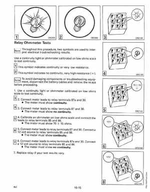
[1] _-' Relay Ohmmeter Tests
Throughout this procedure, two symbols are used to interpret electrical troubleshooting resultsUse continuity light or ohmmeter calibrated on low ohms scale to test continuity
[!] This symbol indicates continuity or very low resistanceThis symbol indicates no continuity, very high resistance00
141DR2149 -'
CJ To avoid damaging components or troubleshooting equipment, disconnect the battery cables and remove the relays before proceeding 1Use continuity light or ohmmeter calibrated on low ohms scale to test continuity
[!] 2Connect meter leads to relay terminals 87a and 30 The meter must show continuity3Connect meter leads to relay terminals 87 and 30 The meter must show no continuityDR2149