1991 Johnson/Evinrude Models "EI" 40 thru 55 Service Manual, Page 305Get this manual
151 6Reposition fuel manifold to make room for the routing of electrical cables7Remove fuel connector bracket and lay to the side of the lower engine cover1sl 8Route the power tilt and trim cable past starter and opening in lower cover and air silencerf71 9Route battery cables in the same manner with the narrow l!J side of the cable facing downf81 10Route remote control electrical harness into lower motor coverPosition harness and connector so they will not interfere with the upper motor cover when installed11Route the VRO tank wires along the same path
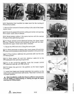
191 12Raise grommet to expose slotLeave power tilt and trim
facmg down
motor wire and sleeve assembly in position in the grommet