1991 Johnson Evinrude EI 60 Loop V Models 150, 175 outboards Service Manual, Page 200Get this manual
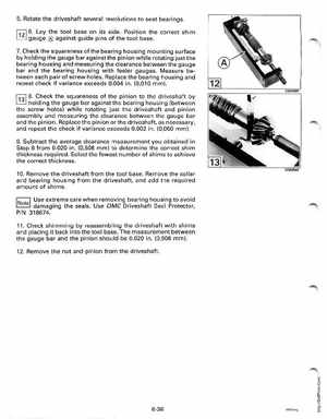
5Rotate the driveshaft several revolutions to seat bearingsf121 6Lay the tool base on its sidePosition the correct shim gauge against guide pins of the tool base7Check the squareness of the bearing housing mounting surface by holding the gauge bar against the pinion while rotating just the bearing housing and measuring the clearance between the gauge bar and the bearing housing with feeler gaugesMeasure between each pair of screw holesReplace the bearing housing and repeat check if variance exceeds 0.004 in(0,010 mm)r:;:;l 8Check the squareness of the pinion to the driveshaft by LJ holding the gauge bar against the bearing housing (between the screw holes) while rotating just the driveshaft and pinion assembly and measuring the clearance between the gauge bar and the pinionReplace the pinion or the driveshaft, as necessary, and repeat the check if variance exceeds 0.002 in(0,050 mm)9Subtract the average clearance measurement you obtained in Step from 0.020 in(0,508 mm) to determine the correct shim thickness requiredSelect the fewest number of shims to achieve the correct thickness10Remove the driveshaft from the tool baseRemove the collar and bearing housing from the driveshaft, and add the required amount of shimsUse extreme care when removing bearing housing to avoid damaging the sealsUse OMC Driveshaft Seal Protector, PIN 31867411Check shimming by reassembling the driveshaft with shims and placing it back into the tool baseThe measurement between the gauge bar and the pinion should be 0.020 in(0,508 mm)12Remove the nut and pinion from the driveshaft 6-36