1991 Johnson Evinrude EI 60 Loop V Models 150, 175 outboards Service Manual, Page 103Get this manual
Principles of Operation Flywheel
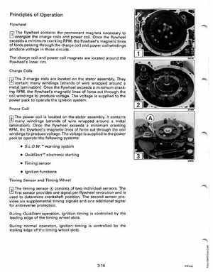
L!.l errergize the charge coils and power coilOnce the flywheel
flywheel contains the permanent magnets necessary to
exceeds minimum cranking RPM, the flywheel's magnetic lines of force passing through the charge coil and power coil windings produce voltage in those circuitsThe charge coil and power coil magnets are located around the flywheel's inner rimCharge Coils
f21 The charge coils are located on the stator assemblyThey
contain many windings (strands of wire wrapped around metal lamination)Once the flywheel exceeds minimum cranking RPM, the flywheel's magnetic lines of force cut through the coil windings to produce voltageThe voltage is supplied to the power pack to operate the ignition systemPower Coil
f21 The power coil is located on the stator assemblyIt contains
many windings (strands of wire wrapped around metal lamination)Once the flywheel exceeds minimum cranking RPM, the flywheel's magnetic lines of force cut through the coil windings to produce voltageThe voltage is supplied to the power pack to operate the following systems: