1990 Johnson Evinrude "ES" 9.9 thru 30 Service Manual, P/N 507871, Page 108Get this manual
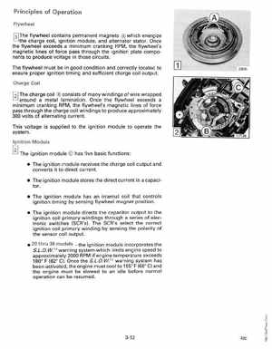
Principles of Operation Flywheel [TIThe flywheel contains permanent magnets which energize the charge coil, ignition module, and alternator statorOnce the flywheel exceeds minimum cranking RPM, the flywheel's magnetic lines of force pass through the ignition plate components to produce voltage in those circuitsThe flywheel must be in good condition and correctly located to ensure proper ignition timing and sufficient charge coil outputCharge Coil f'2l The charge coil consists of many windings of wire wrapped around metal laminationOnce the flywheel exceeds minimum cranking RPM, the flywheel's magnetic lines of force pass through the charge coil windings to produce approximately 300 volts of alternating currentThis voltage is supplied to the ignition module to operate the systemIgnition Module The ignition module has five basic functions: The ignition module receives the charge coil output and converts it to direct current The ignition module stores the direct current in capacitor The ignition module has an internal coil that controls ignition timing by sensing flywheel magnet position The ignition module directs the capacitor output to the ignition coil primary windings through series of electronic switches (SeR's)The SeR's select the correct ignition coil primary winding by sensing the polarity of the sensor coil output